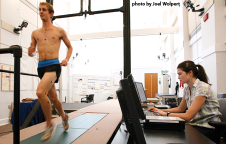
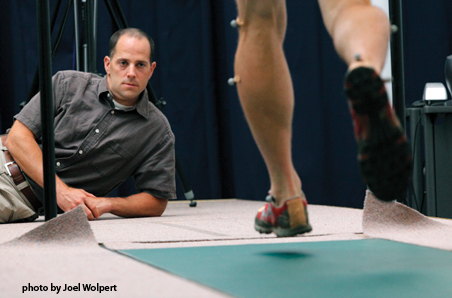
 The Gait and Motion Laboratory at the Department of Physical Medicine and Rehabilitation at the University of Virginia encompass 1,400 square feet and is available for private rental. And who could be blamed for never wanting to run again on a treadmill at the local gym after being spoiled on this state-of-the-art machine with computerized biofeedback?
It is equipped with the following equipment:
• A customized, instrumented treadmill built by AMTI (Advanced Mechanical Technology, Inc.) which includes three treadmill force plates and two staggered force plates embedded in the floor to measure ground reaction forces. These force platforms, in conjunction with the motion analysis system, allow for the estimation of joint torques during extended periods of walking.
• A state-of-the-art motion analysis system (VICON 624, with 10 cameras featuring 1.3 megapixel CCDs) which allows for the highest possible resolution available worldwide.
• The treadmill computer is synchronized with the motion analysis system computer.
• Treadmill Technical Approach:
◦ There are a total of three separate treadmills.

The rear treadmill is 24 inches wide by 54 inches long. This is primarily used for running. Two treadmills, each 12 inches wide by 54 inches long, are mounted in front of the larger single treadmill. These units are primarily used for walking when an individual has a wide stance. One of the smaller units can be used in conjunction with the larger unit for walking when the patient or subject has more of an “in line” walk. The front treadmills each have small diameter rear rollers in close proximity to small diameter rollers on the front of the rear treadmill. This allows the user to transition from one treadmill to the other with only a small perceptible change while wearing footwear. All treadmills move at the same speed.
◦ Three force platforms, one under each belt, are used to allow independent measurement of both feet on the treadmill. The force measurement system is incorporated into this treadmill in a manner which eliminates several possible sources of measurement error. Basically, each force plate consists of a top plate and a base plate connected by four strain elements. In this system design, each belt and driver system is entirely attached to the top plate, while the base plate will be attached to the “ground”. This eliminates the measurement of any forces generated by the treadmill mechanism, for example – belt friction, and focuses on measuring the reaction forces of the foot with the ground. These reaction forces and the weight of the treadmill are the only forces measured by the force sensor. The base of this force platform is attached to the support frame of the treadmill.
◦ AMTI strain gauge amplifiers provide signal conditioning for the strain gauges. The output is six signals corresponding to the six components of force and moment. The entire treadmill including the drive mechanism and force measurement systems is 60 inches wide and 137 inches long. It is 12.5 inches high in the non-inclined state. Cover plates are provided all around the treadmills and removable guardrails are provided. The treadmill is capable of simulating up to a 25% grade in either direction. This is accomplished using pairs of double ended hydraulic pistons at each end of the treadmill. When an uphill run is simulated, the treadmill end facing the subject is raised and when downhill running is intended, the end behind the subject is raised.
• Force Sensing Treadmill Specifications:
◦ Treadmill Surface Size: 24” wide x 108”long consisting of three Units – One “Running” Unit 24” wide x 54” long behind two “Walking” units – each 12” wide by 54” long.
◦ Treadmill Spacing: The spacing between the rollers of the running unit and the walking units and the spacing between the walking units is no greater than 4 mm.
◦ Speed: The treadmill is capable of running 0-12 MPH.
◦ Grade: The treadmill is capable of operating from 0 to 25% grade in both the uphill and downhill direction.
◦ Load: The treadmills can handle up to a 400 LB test subject while walking, running, or performing other related activities.
◦ Force Measurement Capabilities: The system is able to independently measure Fz, Fx, Fy, Mz, Mx, and My on each treadmill. The system should provide signals adequate to determine the center of pressure (COP). The load range for vertical forces applied to the treadmill should be 2000 lb. above the weight of the treadmill.
◦ Calibration: The force plates are installed in the treadmill using both a static and dynamic calibration.
◦ Safety Railings: The treadmill has removable front and side railings surrounding the running surface. These can be easily installed or removed from the treadmill.
◦ Power Requirements: The treadmill is powered by 208/240 VAC three-phase electric power.
For more information, go here:
